BUILDING THE INPUT FILES FOR THE MCSHAPE CODE
The user has to create only two input files to define the target composition and the configuration of the X-ray source, respectively.
These files can be created using a text editor. A simple interactive program is under construction to edit these two data files in the format requested by MCSHAPE v.2.60. The preprocessing code MCinput v 2.10 can be used to edit a sample with only ONE layer (click here for an interactive example).
Warning! MCSHAPE v2.60 is not compatible with earlier versions of MCinput 2.10!
In what follows, there is a short description of these input files, illustrated with a simple example.
Let us assume as example a target of water having 0.5 cm thickness.
- SAMPLE.DAT - The following file gives the sample composition.
- AM241.DAT - This file contains the geometrical configuration and the characteristics of the source.
mcshape 203 version compatibility monodimensional transport model 1 number of layers 2 number of elements H 1 0.1119 chemical symbol atomic number concentration O 8 0.8881 1.0 density [g/cm3] 0.5 thickness [cm]
It should be created within the directory SAMPLES\WATER
Example (Am-241 source):
mcshape 203 version compatibility monodimensional transport model 1 number of energy bins 59.54 1.0 1.0 0.0 0.0 0.0 bin energy [keV], bin weight, Stokes pars. I, Q, U and V
It should be created within the directory SOURCES
3. GEO45_45.DAT - This file contains the geometrical set-up
|
|||||||||||||||
It should be created within the directory GEOMETRY
Note on the reference system.
The incident and the take-off angle (respectively, direnction of the source and position of the detector) define the geometry of the simulation. The refence system is shown in the figure below:
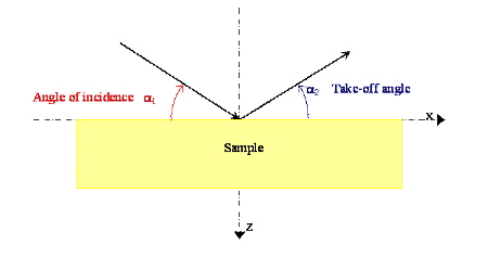
Angle of incidence: the negative X-axe is the reference axe. The angle has to be expressed in degrees (clockwise)
Take-off angle: the positive X-axe is the reference axe. The angle has to be expressed in degrees (anticlockwise).
©Copyright 2006
ALMA MATER STUDIORUM - Università di Bologna
Via Zamboni, 33 - I-40126 Bologna